Radio-4-Matic - AC power update
posted in Electronics by Cargo Cult on Sunday June 30 2013
Analogue electronics? Terrifying. And something other than the Sunday Things? Heresy!
...
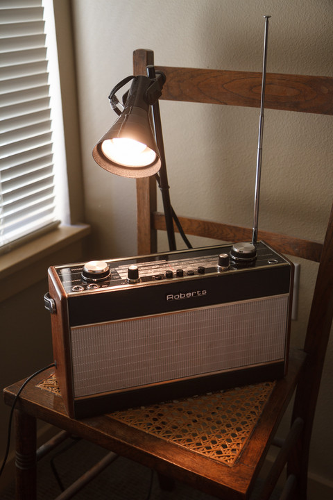
I suspect more through luck than judgement, I've successfully upgraded the Radio-4-Matic to run completely on mains power - it no longer has batteries powering the vintage radio side. (The batteries I'd put in did last a shockingly long time. '70s hardware is efficient! That, and chunky modern alkaline C-cells store a mighty kick.)
The whole thing now has a modern mains-AC-to-12V-DC power brick powering everything, routed in via the hole on the radio originally intended for that very purpose. Although I suspect the late-'60s circuit designers quite possibly weren't expecting the radio to contain a computer as well - there's a 12V-DC-to-5V-DC converter inside there too, with the Raspberry Pi hanging off that. The 5V DV phone charger I'd previously been using to power the Pi is now powering another Pi...
It's been up and running in its new mains-powered guise for over a month now, so I suppose I can declare it to be reliable and stable - and it's definitely time to document my work.
First up, the LM2596S Low Ripple DC-DC Adjustable Step down Power Supply Module I bought at great expense on eBay, and the actually-fairly-expensive 12V 5A switching power supply from Adafruit.
I found much cheaper 12V power supplies on Amazon and the like, but I wanted something that would produce as little noise as possible - given that it was a switched mode power supply to be connected up to some 1970s hardware of unknown behaviour - and something from a reputable supplier I could shout at if it turned out not to produce as little noise as possible. And yes, 12V at 5A is definite overkill for my needs.
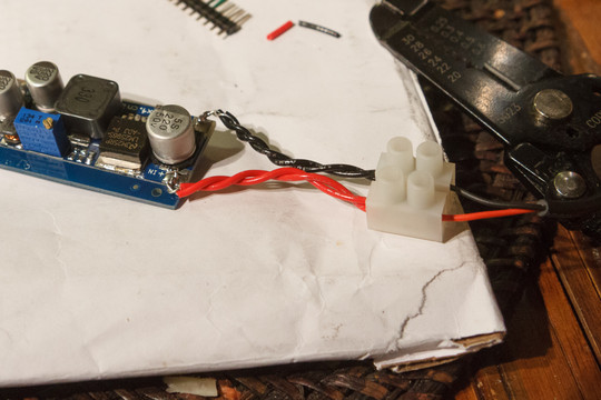
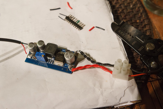
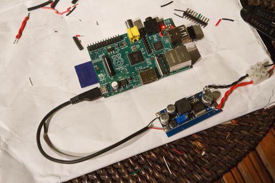
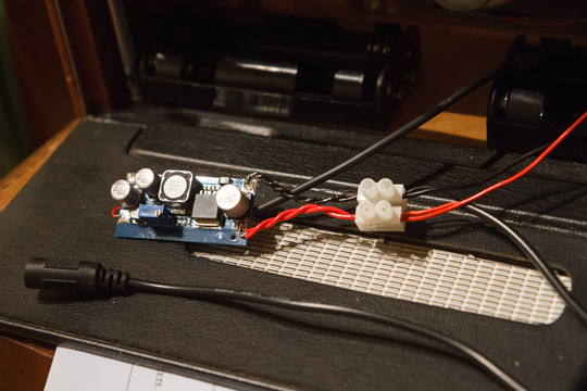
Deciding to go for 'maximum paranoia', I twisted two solid-core wires together for both the positive and negative power inputs, soldering them to the '+ IN' and '- IN' pads on the converter board. The other ends went into a 2-pin terminal block - handy for semi-permanent, high-current connections. Were my new wires thick enough to handle the Pi's power requirements? Almost certainly. I then chopped the male connector off one end of a 2.1mm female/male barrel jack extension cable, stripped the ends of the wires then tinned them with solder. They were red and black, but were they what they claimed to be? The female end of the cable got connected up to the 12V DC adaptor, then I checked voltage and polarity with a multimeter. Yes, the expected way round - red positive, black negative. Satisfied, I disconnected the cable then screwed the wires into the other side of the terminal block.
Time to power up, and adjust the output voltage!
Initially, the DC-DC converter was putting out about 10V. Using a small screwdriver to turn the small brass screw on the blue block, I slowly reduced it to 5.0V, measuring with a multimeter set to 0-20V voltmeter mode. It took a surprising number of turns to get there - the output range is definitely not expressed over a single rotation. I forget which way I had to turn it - I kept turning it in whichever direction gave me an initial voltage drop.
To get that vital electricity from the DC-DC converter into the Raspberry Pi, I decided to use the Micro-USB cable I'd already been using with the phone charger. (It's also possible to get power into the Pi via the GPIO pins.) I chopped off 20cm or so from the Micro-USB end, removed the outer insulation and foil shielding then carefully stripped the ends of the (surprisingly thin) wires inside. My doubled-up wires going into the DC-DC converter? Definite overkill!
There were two promising-looking colours, red and black - but were they really what they presented themselves as being? I have heard of USB cables with completely arbitrary wire colours, and once more it was definitely worth double-checking things...
Cue stripping the ends of the wires on the other section of USB cable. I plugged it into the USB charger, then held the red wire to the positive (red!) probe on a multimeter - set to 0-20V voltmeter mode - then the black wire to the negative (black!) probe. Reading close to 5V. The polarity assignment appeared sensible and correct, but I still needed to triple-check my assumptions.
I plugged the Micro-USB end of the cable into the Raspberry Pi, then checked continuity with the trusty multimeter between 'TP1' on the Pi and the red wire coming out of the cable - yes! Then checked continuity between 'TP2' on the Pi and the black wire - also yes! Definitely looking promising.
The red and black wires were soldered to the appropriate '+' and '-' output pads on the converter, again checking continuity from '+' to 'TP1', then '-' to 'TP2'. All fine there.
Now the moment of truth - actually trying to power the Raspberry Pi with this assembly. With everything connected in this inner arrangement, I reattached the 12V adaptor to the mains...
... It worked! Lights flickered away for a short while, then the blue LED inside the USB WiFi module started flickering. It looks like we have a powered Pi here. SSHing in operated as expected - we have network!
Wanting to check voltage levels again, I set the multimeter back to 0-20V voltmeter mode then checked the voltage between 'TP1' and 'TP2'. Something like 4.85V? Pretty good. Presumably the voltage drop was partially down to those horrifyingly thin wires in the ('official Samsung product') MicroUSB cable. May as well push it up a little to be on the safe side, I decided - so twiddled the voltage adjustment whatsit on the converter to slowly, so slowly move it up to 4.9V, 4.95V, 5.00V. How accurate is my multimeter? No idea - the Pi's input voltage range is apparently 5.00±0.25 V, so I may as well attempt to be slap bang in the middle. If the voltmeter does have an error, I've no idea in which direction.
So that's voltage, what about current? As a quick system load test, I SCP'ed a huge file over its WiFi - something which would trip things up on this elderly Pi before I performed various polyfuse modifications. About a gigabyte of data transferred, solid as a rock. I suppose I could try loading the GPU in some way, but given that this particular Pi is going to be living in a radio for evermore, that much testing seems a little excessive for now.
Time to shut down the Raspberry Pi and work on the radio.
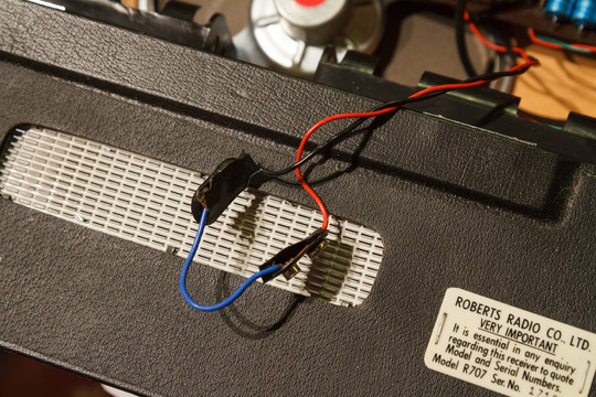
This proved pretty simple. First I removed all the batteries from the radio, then detached the connectors from the battery holders. Then, horrifyingly, I snipped through the red and black wires, stripped the ends of insulation then, for testing, temporarily screwed them into a female 2.1mm jack to screw terminal block, red wire to '+', black wire to '-'. Then I connected it to the 12V adaptor, connected that to the mains, and the radio's hacked-in 3.5mm headphones connector to my laptop. Radiohead out the laptop (as is now traditional), nice and clear Radiohead out the radio. Good news - the power supply could power the radio in a stable manner.
Purists will be relieved that I've kept those original 1970s battery-holder connectors, ready to reattach to the radio should I ever convert it back to its original form!
I drilled a hole in the mysterious black hole-covering plastic cap with a combination of hand-held drill-bit and sharp scissors. (I actually do have an electric drill here in the USA - unfortunately for various obscure reasons it's a 230V 50Hz effort, and barring catastrophes shall never run again.) I poked the wire for the charger through, connector on the outward side - then passed the wire back through the hole in the side of the radio. I then tied a quick, loose loop in the cable and pulled the other side outwards again, ensuring that the internal electronics could never prolapse outwards should the cable be accidentally jerked.
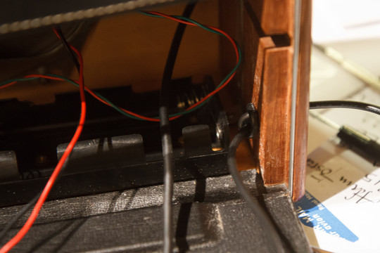
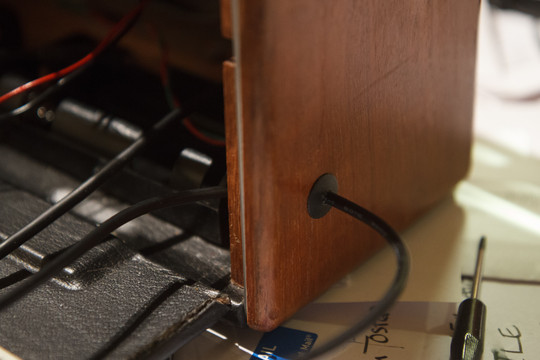
The conveniently colour-coded power input wires from the radio then got clamped into the two-terminal chop-block along with the wires from the power adaptor cable, the 12V-DC-to-5V-DC converter carefully placed in the corner of the now battery-free radio, the Raspberry Pi connected up to my unorthodox, audio-injecting cable before being perched against the battery holders...
Tidy everything up, connect up to the mains and wait for the Pi to boot!
It worked first time - albeit with a slight clicking when the WiFi was running. This interference seemed very much related to the volume level - running alsamixer on the Pi revealed its output level was relatively slow. Push it up near 100% and things are much better - if I run something that sends or receives many packets per second, such as the playback-position-updating mplayer over ssh, then it gives a faint buzz, but most general use is fine.
Playing back any actual audio drowns out the noise pretty effectively. Even with no audio playing (such as leaving the Radio-4-Matic on overnight, to start playing the Today programme in the morning), there's at most a quiet ticking while audio streams in over the WiFi. If anything, it sounds a little like a faint, well-engineered mechanical clock.
Saying all of the above may sound like I'm trying to excuse myself from a shoddy job. The truth is, I've owned multiple computers with far worse audio interference problems - my current gaming PC has unusuable audio from the headphones-out socket on the panel at the front (the back, plus an extension lead, is fine) - while my 2007-era iMac makes squelchy buzzes with headphones connected.
A very faint background clicking when WiFi is used? I suppose I can live with that. Could I cut it down even more with some carefully placed additional components? I shall investigate.
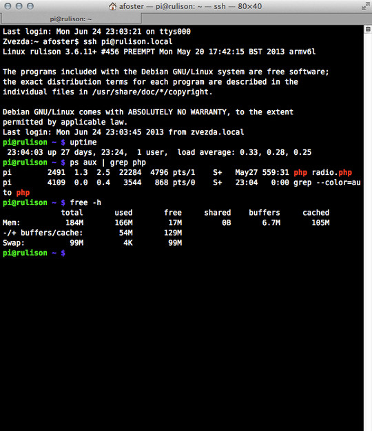
In terms of reliability of the whole thing, I've had the newly reinvigorated Radio-4-Matic running continuously for over a month. My radio.php script has been going for all of that - neatly cleaning up after itself, and somehow not suffering any memory leaks. The radio side gets switched on and off as appropriate via the main volume control - it's very much a radio that emits '70s-transistor-amplified Radio 4 as and when required. Which, typically, is most of the time.
I'm seriously proud of this beast.
Article is now closed for commenting.



1. Good
Posted by phuzz at 2:51AM, Monday July 1 2013
Bloody nice job :)
My folks had a Roberts like that, I wonder if it's still knocking around?